Demo Circuits

To load the files contained on this page you will have to enable loading and saving for the application.

Exclusive-Or

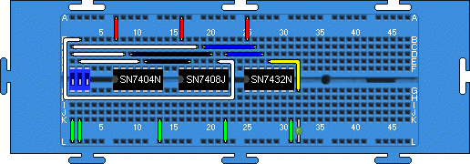
This circuit demonstrates the creation of a basic combinatorial circuit to produce an Exclusive-Or function using three chips with input from a dipswitch and output on a led.  
Exclusive-Or Circuit Diagram
SN7404 - Hex Inverters
SN7408 - Quadruple 2-Input Positive And Gates
SN7432 - Quadruple 2-Input Positive Or Gates

Wired-Or

Another simple combinatorial circuit.  This time we use two buffers with open collector outputs to create a wired-or circuit, ie. by wiring their outputs together they will behave as an Or-gate.

Wired-Or circuit
SN7404 - Hex Inverters
SN7407 - Hex Buffers/Drivers with Open-Collector High Voltage Outputs.

Here the 7404 Inverter is used to make the switch appear to be LOW in off state and HIGH in on state instead of NC and LOW respectively. If connected to the other power rail the switch would effectively be always HIGH as the chips float HIGH with no connection.

Not-S Not-R

This circuit can be used to verify that basic feedback in a circuit works correctly and features two cross-coupled nand gates used to create a Not-S Not-R type flipflop.  The lefthand dip is not-s, the middle not-r.
Not-S Not-R circuit diagram
SN7400 - Quadruple 2-Input Positive Nand Gates

When simulation is started both LEDs will flash on and off.  This is because both switches have been set simultaneously, resulting in an unstable state.  By adjusting one switch a stable state can then be achieved and will remain stable when that switch is returned to its off position.  This is the correct behaviour of this circuit.


Positive Edge-Triggered D-Type

Moving on from the Not-S Not-R type flipflop we combine several of them to produce a posivive-edge triggered D-type flipflop.

Clk - Clock Chip (Set to 100kHz)
SN7404 - Hex Inverters
SN7410 - Triple 3-Input Positive Nand Gates
SN7400 - Quadruple 2-Input Positive Nand Gates

Here the 7404 Inverter is used to make the switch appear to be LOW in off state and HIGH in on state instead of NC and LOW respectively. If connected to the other power rail the switch would effectively be always HIGH as the chips float HIGH with no connection.

4-bit Counter

This circuit shows that larger, more useful circuits can be created and simulated using the Java BreadBoard Simulator.
4-bit counter circuit
Clk - Clock Chip (Set to 1MHz)
SN7474 - Dual D-Type Positive Edge Triggered Flip-Flops with Preset and Clear.

Advancing the simulation by 1 microsecond steps will see the LEDs count 4-bit binary with the most significant bit on the left.  Using the step function will also show that due to the propagation delays that when two led are supposed to light together there is actually a delay between them.

The two dip packages provide preset and clear for the two pairs of bits.